Tight-rope Robotic Arm Model
Introduction to Robotics (Research)
Source:
Department of Mechanical Engineering ,
Massachusetts Institute of
Technology
Introduction to Robotics
ocw.mit.edu for high school documents
kept under MIT licence
Any Robots can be thought as consisting of following parts:
- links
- joints
- actuator
Links
Each rigid body involved in a robot mechanism is called a linkRobot Mechanisms
A robot is a machine capable of physical motion for interacting with the environment. Physical interactions include manipulation, locomotion, and any other tasks changing the state of the environment or the state of the robot relative to the environment. A robot has some form of mechanisms for performing a class of tasks. A rich variety of robot mechanisms has been developed in the last few decades. We will first look at various types of mechanisms used for generating robotic motion.
Joint Primitives and Serial Linkages
A robot mechanism is a multi-body system with the multiple bodies connected together. We begin by treating each body as rigid, ignoring elasticity and any deformations caused by large load conditions. Each rigid body involved in a robot mechanism is called a link, and a combination of links is referred to as a linkage. In describing a linkage it is fundamental to represent how a pair of links is connected to each other. There are two types of primitive connections between a pair of links, as shown in Figure 3.1.1. The first is a prismatic joint where the pair of links makes a translational displacement along a fixed axis. In other Joint Primitives and Serial Linkages
We begin by treating each body as rigid, ignoring elasticity and any deformations caused by large load conditions. Each rigid body involved in a robot mechanism is called a link, and a combination of links is referred to as a linkage. In describing a linkage it is fundamental to represent how a pair of links is connected to each other. There are two types of primitive connections between a pair of links, as shown in Figure 3.1.1. The first is a prismatic joint where the pair of links makes a translational displacement along a fixed axis. In other words, one link slides on the other along a straight line. Therefore, it is also called a sliding joint. The second type of primitive joint is a re-volute joint where a pair of links rotates about a fixed axis. This type of joint is often referred to as a hinge, articulated, or rotational joint.
It is interesting to note that all biological creatures are made of re-volute type joints; there are no sliding joints involved in their extremities.
Combining these two types of primitive joints, we can create many useful mechanisms for robot manipulation and locomotion. These two types of primitive joints are simple to build and are well grounded in engineering design. Most of the robots that have been built are combinations of only these two types .
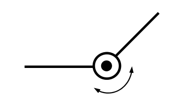
Revolute joint
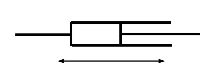
Prismatic joint
Actuators and Drive Systems
Actuators are one of the key components contained in a robotic system. A robot has many degrees of freedom, each of which is a servoed joint generating desired motion. We begin with basic actuator characteristics and drive amplifiers to understand behavior of servoed joints. Most of today’s robotic systems are powered by electric servomotors. Therefore, we focus on electromechanical actuators.
Introduction to Motors
DC Motors
Revolute joint
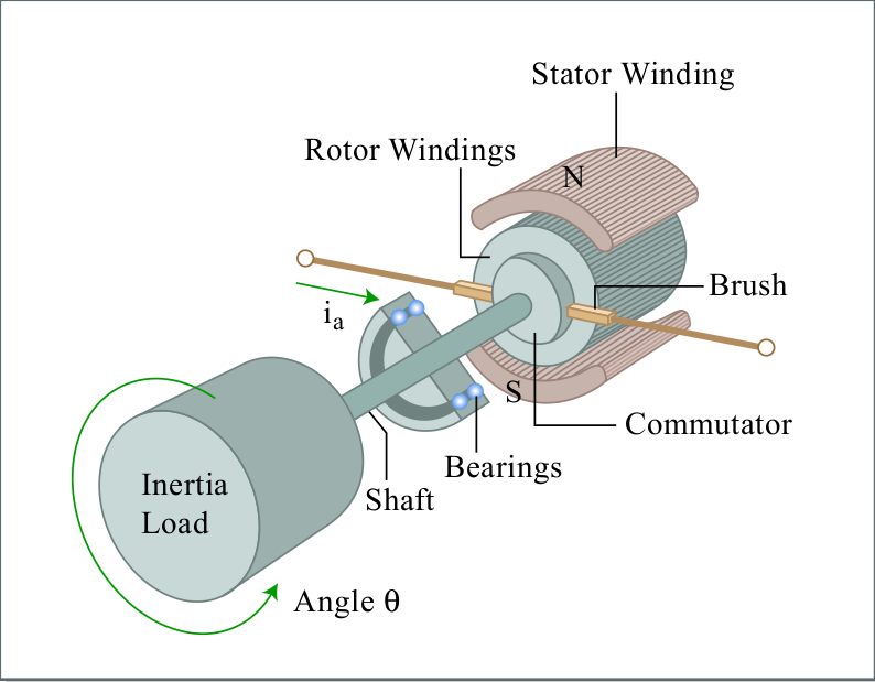
Figure illustrates the construction of a DC servomotor, consisting of a stator, a rotor, and a commutation mechanism. The stator consists of permanent magnets, creating a magnetic field in the air gap between the rotor and the stator. The rotor has several windings arranged symmetrically around the motor shaft. An electric current applied to the motor is delivered to individual windings through the brush-commutation mechanism, as shown in the figure. As the rotor rotates the polarity of the current flowing to the individual windings is altered. This allows the rotor to rotate continually .
Let τ m be the torque created at the air gap, and i the current flowing to the rotor windings. The torque is in general proportional to the current, and is given by
τm = Kt ⋅ i
where the proportionality constant K t is called the torque constant, one of the key parameters describing the characteristics of a DC motor. The torque constant is determined by the strength of the magnetic field, the number of turns of the windings, the effective area of the air gap, the radius of the rotor, and other parameters associated with materials properties.
In an attempt to derive other characteristics of a DC motor, let us first consider an
idealized energy transducer having no power loss in converting electric power into mechanical power. Let E be the voltage applied to the idealized transducer. Th e electric power is then given by E ⋅ i , which must be equivalent to the mechanical power:
Pin = E ⋅ i = τm ⋅ ωm
where ω m is the angular velocity of the motor rotor. Substituting eq.(1) into eq.(2) and dividing both sides by i yield the second fundamental relationship of a DC motor:
E = Kt ωm
The above expression dictates that the voltage across the idealized power transducer is
proportional to the angular velocity and that the proportionality constant is the same as the torque constant given by eq.(1). This voltage E is called the back emf (electro-motive force) generated at the air gap, and the proportionality constant is often called the back emf constant.
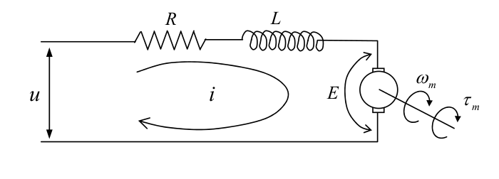
The actual DC motor is not a loss-less transducer, having resistance at the rotor windings
and the commutation mechanism. Furthermore, windings may exhibit some inductance, which stores energy. Figure 2.1.2 shows the schematic of the electric circuit, including the windings resistance R and inductance L. From the figure,
u = R ⋅i + L di/dt +E
where u is the voltage applied to the armature of the motor.
motor circuit
Combining eqs.(1), (3) and (4), we can obtain the actual relationship among the applied
voltage u, the rotor angular
velocity ω m , and the motor torque τ m .
Kt u / R = τm + Te dτm/dt +K t^2 ωm /R
where time constant Te = L/R , called the motor reactance, is often negligibly small. Neglecting this second term, the above equation reduces to an algebraic relationship:
τm = Kt /Ru − Kt^2/Rωm
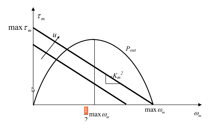
This is called the torque-speed characteristic. Note that the motor torque increases in proportion to the applied voltage, but the net torque reduces as the angular velocity increases. Graph below illustrates the torque-speed characteristics. The negative slope of the straight lines, − Kt^2/ R , implies that the voltage-controlled DC motor has an inherent damping in its mechanical behavior. The power dissipated in the DC motor is given by
Pdis=Ri^2=R/Kt^2 τm^2
from eq(1). Taking the square root of both sides yields
(Pdis )^(1/2)=τm/Km , Km =Kt/(R)^(1/2)
where the parameter K m is called the motor constant. The motor constant represents how effectively electric power is converted to torque. The larger the motor constant becomes, the larger the output torque is generated with less power dissipation. A DC motor with more powerful magnets, thicker winding wires, and a larger rotor diameter has a larger motor constant. A motor with a larger motor constant, however, has a larger damping, as the negative slope of the torque-speed characteristics becomes steeper, as illustrated in above graph.
graph
Taking into account the internal power dissipation, the net output power of the DC motor is given by
Pout = τ m ⋅ ωm = ( Kt/Ru − Km ωm ) ωm
This net output power is a parabolic function of the angular velocity, as illustrated in above graph. It should be noted that the net output power becomes maximum in the middle point of the velocity axis, i.e. 50 % of the maximum angular velocity for a given armature voltage u. This implies that the motor is operated most effectively at 50 % of the maximum speed. As the speed departs from this middle point, the net output power decreases, and it vanishes at the zero speed as well as at the maximum speed. Therefore, it is important to select the motor and gearing combination so that the maximum of power transfer be achieved.